Build Your Own Yagi Antenna: Boost Signal & Save Money!
Are you tired of weak, unreliable signals? Do you dream of extending the range of your Wi-Fi, hitting distant ham radio repeaters, or even communicating with satellites? For many, the answer to these frustrations lies not in expensive commercial equipment, but in the rewarding world of do-it-yourself (DIY) projects. Specifically, building your own **DIY Yagi antenna** can be a game-changer, offering superior directional performance at a fraction of the cost.
This comprehensive guide will walk you through everything you need to know about constructing your very own Yagi antenna. From understanding the basic principles to selecting materials, designing, building, and testing, we’ll demystify the process. You’ll discover how a homemade Yagi can dramatically improve your reception and transmission capabilities, providing a satisfying blend of technical achievement and practical utility. Get ready to transform your signal strength and unlock new possibilities with a custom-built antenna!
Table of Contents
- Understanding the Yagi Antenna: A Brief Overview
- Why Build a DIY Yagi Antenna? The Unbeatable Advantages
- Essential Tools and Materials for Your DIY Yagi Project
- Designing Your Yagi: Precision is Key
- Step-by-Step Construction Guide for Your Homemade Yagi
- Tuning and Testing Your DIY Yagi Antenna
- Practical Applications and Beyond: What Your DIY Yagi Can Do
- Safety Considerations and Best Practices
Understanding the Yagi Antenna: A Brief Overview
At its core, a Yagi-Uda antenna (commonly just "Yagi") is a directional antenna system first invented by Shintaro Uda and Hidetsugu Yagi in 1926. Unlike an omnidirectional antenna that sends and receives signals in all directions, a Yagi focuses its energy in a specific direction, leading to significant gains in signal strength and rejection of interference from other directions. This makes it incredibly effective for point-to-point communication or for zeroing in on a specific signal source. A typical Yagi antenna consists of several key elements mounted on a central boom:- Driven Element: This is the part of the antenna directly connected to your radio or device via a feedline (like coaxial cable). It's typically a dipole.
- Reflector: Positioned behind the driven element (opposite the direction of desired signal propagation), the reflector is slightly longer than the driven element. Its purpose is to reflect signals forward, enhancing the antenna's directivity.
- Directors: Placed in front of the driven element (in the direction of desired signal propagation), directors are typically shorter than the driven element. They help to "direct" the signal, further focusing the beam and increasing gain. A Yagi can have one or many directors; generally, more directors mean higher gain but also a longer antenna and narrower beamwidth.
Why Build a DIY Yagi Antenna? The Unbeatable Advantages
The allure of a **DIY Yagi antenna** isn't just about the satisfaction of building something with your own hands; it's about unlocking a host of practical benefits that often outweigh off-the-shelf solutions. One of the most compelling reasons is the **cost-effectiveness**. As some enthusiasts have noted, "The whip antenna on the radio might let you hear satellites and the ISS, but you’ll get far better reception by making your own yagi antenna, which takes about an hour and costs less than $25 (not including the cost of your radio)." This highlights a significant saving compared to commercial equivalents, especially when considering specialized antennas. Many experienced ham radio operators, like myself, "have always liked to build some of my own ham radio stuff, and tend to be on the cheap side." This DIY approach allows for a "simple, repeatable, method of building cheap" yet effective antennas. Beyond the savings, the **performance boost** is often dramatic. While an omnidirectional antenna might manage to reach 20 kilometers, a directional antenna like a Yagi can achieve "reliable communication over 40 kilometers," effectively doubling your range in certain scenarios. This "far better reception" can be the difference between barely hearing a weak signal and having clear, consistent communication. For those looking to "communicate with amateur radio satellites or to assist in getting into that repeater," a well-built Yagi is often essential. The **versatility** of a **DIY Yagi antenna** is another major advantage. You're not limited to a single frequency or application. You can "make a homemade yagi antenna for the 433 mhz band with copper rods, square tube, and BNC connector" for specific IoT projects or LoRa applications. For ham radio, "today we are going to build a yagi antenna designed for 2 meter and 70 cm ham radio bands." But it doesn't stop there; "it outlines how to build yagis for 144mhz, 220mhz, several different 440 band frequencies, 900 mhz, and 1.2 ghz." You can even construct "antennas for 70, 33 and 23 cm" or "a great 10 or 20 metre yagi (beam antenna) in your attic or loft space." The adaptability extends to non-radio applications too; an "easy to build wifi 2.4ghz yagi antenna" can "extend the range of your wifi or 2.4ghz devices (like surveillance cameras) into many miles and kilometers." Finally, **portability and ease of deployment** are significant benefits. "This lightweight antenna is perfect to use for fox hunts or as a portable directional antenna for public service events." Some designs are so efficient that you can build "a very light weight, cheap, easy to build and deployable in 30 seconds portable VHF antenna for the 2 meter band." This makes them ideal for field operations, emergency communications, or simply taking your hobby on the go.Essential Tools and Materials for Your DIY Yagi Project
Embarking on a **DIY Yagi antenna** project requires a few basic tools and materials, most of which are readily available and inexpensive. The beauty of DIY is often in its simplicity and the use of common household or hardware store items. **General Tools You'll Likely Need:**- **Measuring Tape or Ruler:** Precision is paramount for antenna elements.
- **Drill and Drill Bits:** For creating holes in the boom and elements.
- **Cutting Tools:** Depending on your material, this could be a hacksaw, pipe cutter, or wire cutters.
- **Screwdrivers/Wrenches:** For assembly.
- **Soldering Iron and Solder (Optional but Recommended):** For robust electrical connections, especially for the driven element and connector.
- **Multimeter or Continuity Tester:** To check for shorts or open circuits.
- **SWR Meter/Antenna Analyzer (Highly Recommended):** For tuning and testing your finished antenna.
- **Safety Glasses and Gloves:** Always prioritize safety.
- **Boom Material:** The central support structure. "The boom is a piece of conduit with holes drilled in the appropriate places." PVC pipe, square aluminum tubing, or even wood can be used, depending on the frequency and desired rigidity. For higher frequencies, a non-conductive boom like PVC is often preferred to minimize interaction with the elements.
- **Element Material:** This is where the magic happens. "The antenna is constructed from m4 stainless steel threaded rods, as they are relatively inexpensive and common place at most diy stores." This is an excellent choice because "it is an easy material to work with." Other popular options include "copper rods" or aluminum tubing/wire. The choice often depends on the frequency band; thicker materials for lower frequencies (e.g., 10 or 20 meters) and thinner ones for higher frequencies (e.g., 2.4 GHz).
- **Connector:** To connect your antenna to your radio or device. A "BNC connector" is common for VHF/UHF frequencies, but SO-239 (UHF connector) or N-type connectors are also used. Ensure it matches your feedline and radio.
- **Feedline:** Coaxial cable (e.g., RG-58, RG-8X, LMR-400) to connect the antenna to your radio. Choose a low-loss cable, especially for longer runs or higher frequencies.
- **Mounting Hardware:** U-bolts, clamps, nuts, bolts, washers – whatever you need to secure the elements to the boom and the antenna to its mast or support structure.
- **Insulators (Optional but Recommended):** For electrically isolating the elements from the boom, especially if using a conductive boom. Nylon standoffs or plastic caps can work.
Designing Your Yagi: Precision is Key
The success of your **DIY Yagi antenna** hinges significantly on precise design. Unlike a simple dipole, a Yagi's performance is highly dependent on the exact lengths of its elements and their spacing along the boom. Even small deviations can impact gain, SWR (Standing Wave Ratio), and beam pattern.Software Simulation and Theoretical Measurements
Before you even pick up a drill, it's highly recommended to start with theoretical measurements and, if possible, software simulations. This is where expertise truly comes into play. "Learn how to build a yagi antenna for 433.92 mhz using 4nec2 software." Programs like 4nec2 (a free antenna modeling software) allow you to input "initial and theoretical measurements, the geometry, and the optimization" of your proposed design. You can simulate different element lengths, spacings, and boom materials to see their effect on gain, SWR, and radiation patterns. This virtual prototyping saves time and materials by identifying potential issues before construction. For those without access to simulation software, numerous online calculators and published designs provide excellent starting points for various frequency bands. For instance, you can find established dimensions for "a 3 element yagi with about 7.2 db of forward gain" for the 2-meter band (144 MHz) or designs for "an effective 5el antenna for 6 metres and measurements form producing a 4le 70 mhz antenna." Always ensure you use dimensions specific to your target frequency (e.g., "433 mhz band").Element Dimensions and Spacing
This is the core of Yagi design. Each element—reflector, driven element, and directors—has a specific length relative to the wavelength of your target frequency. Their spacing along the boom is equally critical.- **Reflector:** Typically about 5% longer than the driven element.
- **Driven Element:** Its length is usually approximately half a wavelength at your target frequency (a half-wave dipole). For example, for 433 MHz, the wavelength is roughly 0.69 meters, so a half-wave dipole would be around 0.345 meters or 34.5 cm. However, due to end effects and element diameter, the actual physical length will be slightly shorter.
- **Directors:** Each director is progressively shorter than the one behind it, and slightly shorter than the driven element. Their lengths and spacing are optimized for maximum gain and directivity.
Step-by-Step Construction Guide for Your Homemade Yagi
Once you have your design dimensions, the real fun begins: building your **DIY Yagi antenna**. This "how to build a yagi antenna article is the diy yagi antenna for the 433 mhz production process of the homemade yagi antenna," but the principles apply broadly across different frequencies.Preparing the Boom and Elements
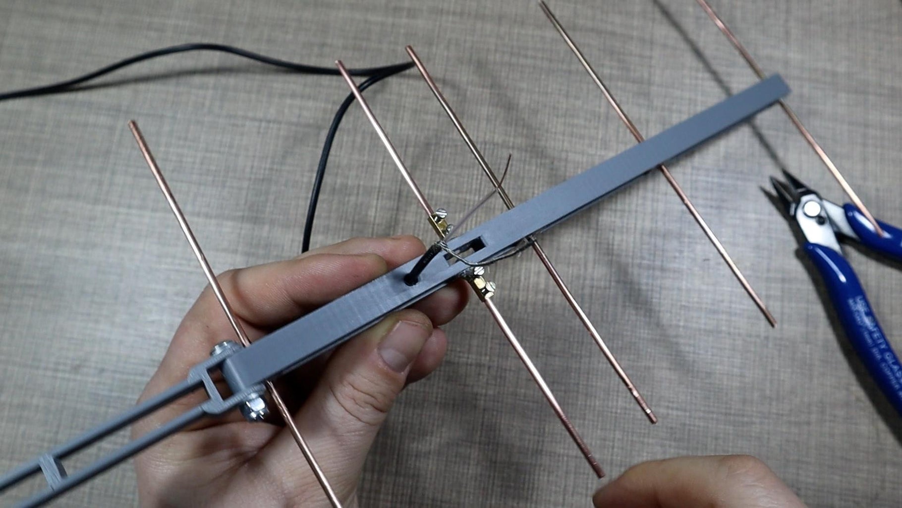
1. **Cut the Boom:** Take your chosen boom material, whether it's "a piece of conduit" or square tubing, and cut it to the required length. This length will depend on the number of elements and their spacing. 2. **Mark Element Positions:** Carefully measure and mark the precise locations for each element along the boom. Accuracy here is crucial. 3. **Drill Holes:** "Drill holes in the appropriate places" for each element. The diameter of the holes should match the diameter of your element material. For conductive elements mounted on a non-conductive boom (like PVC), you can simply drill through. If using a conductive boom (like aluminum square tube), you'll need to ensure the elements are electrically isolated from the boom, often using plastic insulators or standoffs. 4. **Cut and Prepare Elements:** Cut your "m4 stainless steel threaded rods" or "copper rods" to their exact specified lengths for the reflector, driven element, and directors. For the driven element, you'll need to prepare it for connection to your feedline, often by bending it into a dipole shape or creating attachment points. Remember, "the antenna is constructed from m4 stainless steel threaded rods, as they are relatively inexpensive and common place at most diy stores,Additionally, it is an easy material to work with and does."Assembling and Connecting
1. **Mount Elements:** Insert each element into its designated hole on the boom. Secure them firmly. For threaded rods, you might use nuts and washers on either side of the boom. Ensure they are perpendicular to the boom. 2. **Prepare Driven Element:** If your driven element is split (like a dipole), you'll need to attach your coaxial cable here. This typically involves soldering the center conductor to one half and the shield to the other. For impedance matching, you might incorporate a balun (balanced-to-unbalanced transformer) at this point, especially for higher power or to reduce common mode current. 3. **Attach Connector:** Mount your "BNC connector" (or chosen connector type) securely to the boom or a small bracket near the driven element. Connect the coaxial cable from the driven element to this connector. Ensure all connections are robust and weatherproofed if the antenna will be exposed to the elements. 4. **Double-Check:** Before moving to testing, visually inspect all connections, measurements, and element alignments. "By following these instructions, you can" build a reliable antenna.Tuning and Testing Your DIY Yagi Antenna
Building the antenna is only half the battle; tuning and testing are crucial steps to ensure it performs optimally. This is where you verify your design and make any necessary "adjustment of the antenna elements and find out how to improve" its performance. 1. **SWR Measurement:** The most important initial test is to measure the Standing Wave Ratio (SWR). An SWR meter or antenna analyzer is an invaluable tool here. Connect your antenna to the SWR meter, then the meter to your radio. Transmit a low-power signal (if using a radio) or use the analyzer's sweep function across your target frequency band. You're looking for an SWR close to 1:1 (ideally below 1.5:1) at your desired operating frequency.- **What SWR tells you:** A high SWR indicates that your antenna is not efficiently transferring power from your radio to the air. It means the antenna's impedance doesn't match your radio's output impedance (typically 50 ohms).
- **Adjusting SWR:** If the SWR is high, small adjustments to the driven element's length are usually the first step. Shortening the element raises the resonant frequency, while lengthening it lowers it. Sometimes, slight adjustments to director or reflector lengths, or their spacing, can also help, but the driven element is typically the primary tuning point.
Practical Applications and Beyond: What Your DIY Yagi Can Do
A **DIY Yagi antenna** is incredibly versatile, extending its utility far beyond basic communication. Its directional nature makes it ideal for a multitude of specific applications where focused signal power is beneficial. **1. Ham Radio Communications:** * **Satellite Communication:** "The whip antenna on the radio might let you hear satellites and the ISS, but you’ll get far better reception by making your own yagi antenna." A Yagi is crucial for working amateur radio satellites, allowing you to track and communicate with them as they pass overhead. "This antenna can be used to receive the ham satellite communications with any portable UHF" radio. * **Repeater Access:** For ham operators struggling to hit distant repeaters, a **DIY Yagi antenna** can provide the necessary gain and directivity to "assist in getting into that repeater," especially on bands like "2 meter and 70 cm ham radio bands." * **Fox Hunts and Direction Finding:** "This lightweight antenna is perfect to use for fox hunts or as a portable directional antenna for public service events." Its ability to pinpoint a signal source makes it invaluable for these activities. **2. Wi-Fi and 2.4 GHz Devices:** * **Extended Wi-Fi Range:** An "easy to build wifi 2.4ghz yagi antenna" can dramatically "extend the range of your wifi or 2.4ghz devices (like surveillance cameras) into many miles and kilometers." This is perfect for long-distance point-to-point Wi-Fi links or improving the signal to outdoor cameras. * **IoT and LoRa Applications:** For those experimenting with Internet of Things (IoT) devices or LoRa networks, a custom "433 mhz band" Yagi can provide the focused power needed for reliable long-range data transmission. **3. Specialized Frequencies and Bands:** * The flexibility of DIY allows you to build Yagis for almost any frequency. "It outlines how to build yagis for 144mhz, 220mhz, several different 440 band frequencies, 900 mhz, and 1.2 ghz." You can also tackle lower frequencies like "10 or 20 metre yagi (beam antenna)" or "6 metres" (50 MHz), or even higher ones like "70, 33 and 23 cm" (420 MHz, 900 MHz, 1.2 GHz). **4. Discreet Installations:** * For those with HOA restrictions or who prefer a less visible antenna, a Yagi can often be constructed "in your attic or loft space." While attic installations might experience some signal loss due to roofing materials, a well-designed Yagi can still offer significant improvements over indoor omnidirectional antennas. **5. Portable and Emergency Communications:** * The light weight and simple construction of many **DIY Yagi antenna** designs make them ideal for portable operations. As mentioned, some can be "deployable in 30 seconds portable VHF antenna for the 2 meter band," making them perfect for field days, camping trips, or emergency communication kits. The possibilities are vast, limited only by your imagination and the fundamental principles of antenna design.Safety Considerations and Best Practices
While building a **DIY Yagi antenna** is a rewarding project, it's crucial to prioritize safety throughout the process. Working with tools, electricity, and potentially elevated structures carries inherent risks. 1. **Tool Safety:** Always use appropriate personal protective equipment (PPE), such as safety glasses and gloves, when cutting, drilling, or soldering. Ensure your tools are in good working condition and use them as intended. Be mindful of sharp edges on cut materials. 2. **Electrical Safety:** * **Low Power Testing:** When testing your antenna with a radio, always start with the lowest possible power setting. * **RF Exposure:** While the power levels for most DIY Yagi applications (like ham radio VHF/UHF or Wi-Fi) are relatively low, it's good practice to avoid prolonged exposure to the antenna's direct radiation path, especially during transmission. Understand the concept of RF exposure limits. * **Connections:** Ensure all electrical connections (especially to the driven element and connector) are well-insulated and secure to prevent shorts. 3. **Antenna Mounting Safety:** * **Height and Stability:** If mounting your Yagi outdoors or on a mast, ensure the mast is sturdy and securely anchored. Consider wind loading, especially for larger antennas. *

Detail Author:
- Name : Jade Quitzon
- Username : streich.easter
- Email : billie28@yahoo.com
- Birthdate : 1978-08-11
- Address : 46424 Schimmel Points Port Ernie, IL 40056-5165
- Phone : (689) 912-9172
- Company : D'Amore, Schoen and Davis
- Job : Precious Stone Worker
- Bio : Molestiae non aut nostrum vitae rerum aliquid perspiciatis tenetur. Pariatur expedita sit officiis est voluptatibus tempora. Deleniti consequatur ex possimus enim. Et quos quo et provident et.
Socials
tiktok:
- url : https://tiktok.com/@lenoremurazik
- username : lenoremurazik
- bio : Quis omnis est enim voluptatum.
- followers : 2131
- following : 1720
facebook:
- url : https://facebook.com/murazikl
- username : murazikl
- bio : Harum beatae non ducimus fugit facilis non sit. Iste qui tenetur placeat non.
- followers : 3790
- following : 2451
